Introduction to agitator design:
Agitators are machines used in industries for mixing fluids. In industries mixing of fluids is necessary for many chemical processes. It may include mixing of liquid with liquid, gas with a liquid, or solids with liquid. Mixing is accomplished by the rotating action of an impeller in the continuous fluid. Type of fluid and its physical state, the degree of agitation and geometry of vessel are key factors in the design and selection of agitator components.
Here we will discuss the design of agitator
vessel based on practical data inputs as given below:
Inputs for agitator design:
Design pressure: 6 kg/cm
2 / F.V.
Design temperature: 75°C to 200°C
Vessel working capacity: 6.3 KL
Vessel inside diameter (D): 1950 mm
Vessel T.L.-T.L. length: 2200 mm
Maximum mixing speed (N): 150 RPM
Density of working fluid: 1000 kg/m
3
Viscosity of working fluid: 10000 CP
MOC: Hastelloy C-22
Solution:
Step-1: Power calculations and selection of motor
For required power calculations, selection of the type of impeller is very important to achieve required agitation power. Selection of impeller is done based on application and type of flow. Flat paddle, turbine, anchor type, pitched blade impellers are used most commonly. For given type of agitation flat paddle impeller is used as given below:
After selection of impeller dimensionless number Reynold’s number is calculated as given below
Re = ρ*N*d
5/ µ
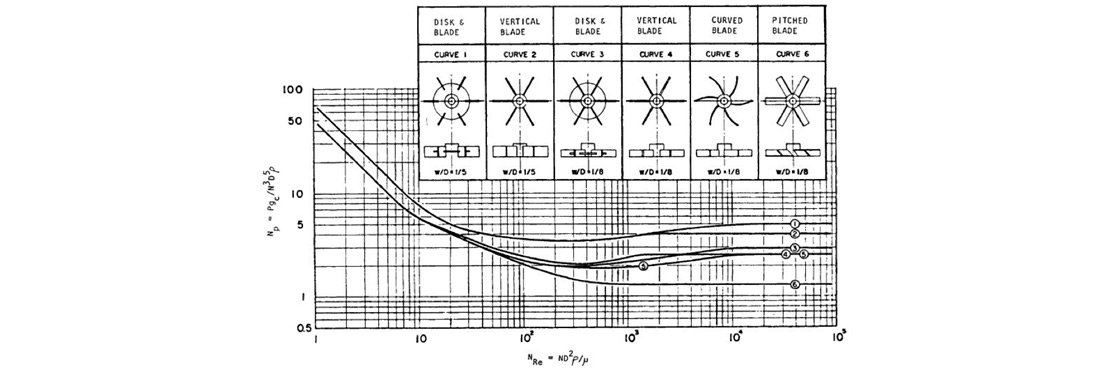
From generic agitator curve, as shown in Fig.1, impeller power number is calculated based on calculated Reynold’s number.
Fig. 1 – Power number against Reynolds number of some turbine impellers [Ref. Bates, Fondy, and Corpstein, Ind. Eng. Chem. Process. Des. Dev.
2(4) 311 (1963)]
Based on impellers selected the layout of the shaft is done as shown in Fig.2.
Fig.2 Agitator assembly layout
Step 2: Design of shaft
Design of solid shaft subjected to shear stress
For selected motor power rated torque and maximum torque is calculated as given below:
Rated torque: Tr = P*4500 / 2*π*N
Maximum torque: Tm= (1.5 to 2.5) Tr
Therefore, solid shaft diameter is calculated by
Tm = π* ζ*ds
3/16
Step:3 Design of solid shaft subjected to pure bending
Maximum bending force is assumed to be acting at the point of jamming i.e. 0.75 of maximum agitator radius from the axis.
Maximum bending force Fm = Tm/0.75*r
Maximum bending moment Mm= π*бb*ds
3/32
Step:4 Design of solid shaft subjected to bending and twisting
According to maximum shear stress theory for ductile material, equivalent twisting moment is calculated as
Te = √(Mm
2+Tm
2) = π* ζ*ds
3/16
According to maximum normal stress theory for brittle material, equivalent bending moment is calculated as
Te = ½ ( Mm+√(Mm
2+Tm
2) ) = π*бb*ds
3/32
Larger of all calculated diameters is considered as the minimum required diameter of the shaft. Therefore, selecting shaft diameter of 100mm, the shaft is checked for critical speed.
Step:5 Design of solid shaft based on critical speed
Maximum deflection (∆) due to bending force and corresponding critical speed (Nc) is calculated as follows,
∆ = WL
3 / 3EI
Nc = 946/√∆
Agitator should be designed to operate at less than 70% of the critical speed. Since selected 100mm dia. shaft is failing at critical speed, select next standard shaft of diameter 120mm and perform the calculations for critical speed.
Thus required solid shaft diameter is 130mm.