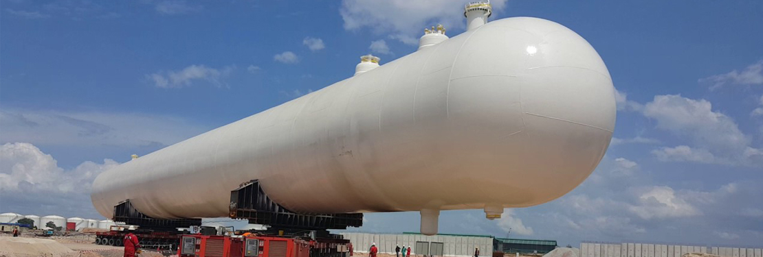
This article is based on guidelines given in EEMUA 190. Design of mounded bullet is carried out as per PD 500 as suggested in EEMUA 190 (unless specified by the customer). Other codes like ASME also can be used for design calculations. Design of shell courses for internal and external pressure at given design conditions is done as per specified design code. Selection and arrangement of stiffening ring have large impact on design thicknesses. Once bullet shell and dish end thicknesses are finalized, whole equipment is considered under following loads:
Load 1- Dead weight of the vessel (Q1)
Dead weight of the vessel is fabricated empty weight of the vessel. It is given as
Q1 (N) = Empty weight(w2) * 9.81
Load 2- Weight of liquid fill (Q2, Q2’)
Weight of liquid fill is considered for both working fluid and water. The weight of liquid is considered for 100% fill of liquid in the vessel
For operating fluid,
Q2 (N) = Density of operating fluid (kg/m3) * Liquid fill (m3) * 9.81 (m/s2)
For water,
Q2’ (N) = Density of water (kg/m3) * Liquid fill (m3) * 9.81 (m/s2)
Load 3- Internal design pressure (Q3, Q3’)
Internal design pressure is considered for both design pressure and hydro test pressure. Specified design pressure is considered along with the static head of the fluid
For design case,
Q3 (MPa) = Specified internal design pressure (MPa) + Fluid static head (MPa)
For the hydro test case,
Q3’ (MPa) = Specified hydro test pressure (MPa) + Water static head (MPa)
Where,
Static head (MPa) = Density of fluid/water (kg/m3) * 9.81(m/s2) * Fill height (m) * 10-6
Load 4- Negative internal design pressure (Q4)
Negative internal design pressure causes compressive stresses in shell plates and stiffening rings. The negative internal pressure should be taken as -0.5 bar, unless agreed otherwise specified.
Load 5- Pressure due to the mound (Q5)
• The pressure of mound on the cylinder
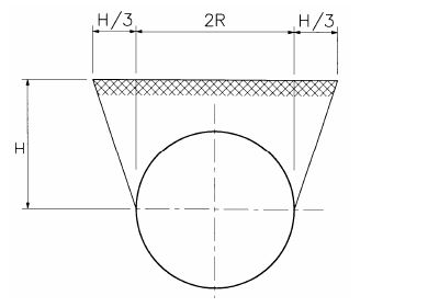
The weight of the mound assumed to be resting on top of the cylinder is
Q5 (kN) = (2RH − πR2/2 + H2/3) x γs x L
Where,
γs = weight of soil per m3 (kN/m3)
H = mound depth (m)
R = shell outer radius (m)
L = Vessel T.L.- T.L. length (m)
The pressure of mound is zero at the center of the cylinder.

• Pressure by mound on domed ends
Mound exerts pressure on domed ends of the vessel. This soil pressure (ps) increases linearly with the depth.
ps (kN/m2) = C x γs x h
Where,
C = soil pressure coefficient
h = mound depth (m)
Pressure by mound on domed end is maximum at the center and minimum at the top of it.
Load 6 – Load due to the uneven support of the vessel (Q6)
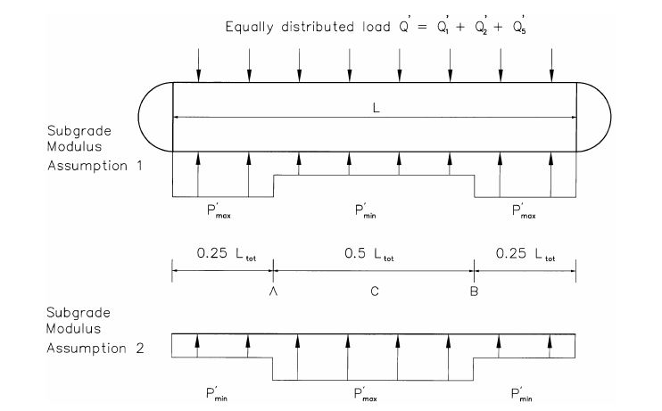
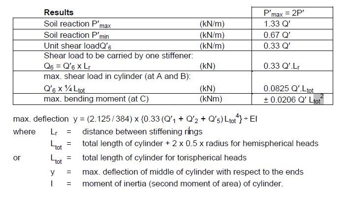
Determination of uneven support, two calculations need to be made as given below using design shell thicknesses and loads Q1, Q2, and Q5.
• Using Annexure-C from EEMUA code


• Carry out a ‘beam on elastic foundation’ analysis, using the long-term subgrade moduli determined in the soil investigation. The calculation is usually carried out using a finite element method.
From these two calculations, governing result is to be used for the stiffener design i.e. resulting Q6.
Load 7- Load due to changes in the vessel length (Q7)
Axial loads need to be considered for the verification of longitudinal stresses. When the vessel expands or contracts due to temperature or pressure variations, the surrounding soil will exert a frictional force on the vessel. A coefficient of friction = 1 is conservative. The unit friction force Fsoil will be:
Fsoil = Q1 + Q2 + 2Q5 (kN/m)
The axial load due to friction will be maximum at mid-span of the vessel and will be equal to Fsoil X half vessel length, provided the movement of the vessel is enough to develop the full friction.
The resulting longitudinal stress due to friction will be compressive if the vessel expands, and tensile if the vessel contracts. When the vessel expands, the soil pressure on the domed ends will increase, which will result in an increased axial compressive load.
Load 8- Seismic load (Q8)
The effect of earthquakes on design loads may need to be taken into account. The effect of the horizontal acceleration should be taken into account as a horizontal lateral force. This force is equal to the percentage mentioned above of the weight (loads 1, 2 and 5). Sometimes a vertical acceleration due to the earthquake is also specified, which is taken into account by increasing the weight proportionally. The resultant of the horizontal force and the (increased) weight needs to be determined separately for loads 1, 2 and 5.
Load 9- External Pressure Caused by Explosion of Gas Clouds (Q9)
If the overpressure and the reflection coefficient are used, the pressure to be taken into account is 1.5 x 15 = 22.5 kN/m2. The load per stiffening ring is:
Q9 = (2R + ⅔ H) x L x 22.5 (kN)
Q9 may be considered as an increase in the weight of the mound and should be treated in the calculations in the same manner as Q5.
Load 10- Supporting pressure by the foundation (Q10)
The supporting load P by the sand-bed foundation to be allocated to one stiffening ring is the maximum of the two analyses: using the assumed support distribution from Appendix C and the ‘beam on elastic foundation’ approach as mentioned in Load-6
When using the assumed support distribution from Appendix C:
P = 1.33 x {Q1 + Q2 + Q5 (+ Q9, if applicable)} (kN)
When using the beam on elastic foundation approach:
P = P’ x L (kN)
where P is the maximum unit support load
It is assumed that the sand-bed will exert a radial pressure on the cylinder. The angle over which the cylinder is supported depends on the foundation, but for a properly prepared sand bed an angle of 120° is a realistic assumption.
Conservatively, it is assumed that pressures are cosine-like distributed according to:
p = p0 cos {1.5 (180° − ψ)} for 120° < ψ < 240°
The maximum pressure p0 at ψ = 180° is:
p0 = P/(1.2 x R x L) (kN/m2)

This pressure is to be added to the negative internal pressure when determining the shell plate thickness of the cylinder. During construction and initial hydro test, it may be advantageous to support the vessel on a narrower foundation, for instance, a support angle of 90° (ψ0 = 135°) or even (as a minimum) 60° (ψ0 = 150°).
For those cases the maximum pressure exerted by the foundation will be:
90° support angle: p0 = P/(0.943 x R x L) (kN/m2)
60° support angle: p0 = P/(0.65 x R x L) (kN/m2)
