Pressure vessel hydrostatic test requirements and implications on design

For hydro test as per ASME code manufacturer of the equipment must follow ASME Boiler and Pressure Vessel Code Section VIII DIV.1 (Rules for Construction of Pressure Vessels), UG-99. We will discuss hydro test requirement in this discussion. Requirements as per ASME Boiler and Pressure Vessel Code Section VIII DIV.1 (Rules for Construction of Pressure Vessels), UG-99 –
  • Before hydro test all operations must be completed as no one can alter equipment thicknesses once hydro test is done.
  • All examinations (eg. all NDT tests) have to be performed, except those required after the hydro-test.
  • Hydrostatic test pressure at every point in the vessel is at least equal to 1.3 times the maximum allowable working pressure multiplied by the lowest stress ratio (LSR) for the materials of which the vessel is constructed.
Hydro test Pressure = 1.3 x Design Pressure x LSR. LSR=  (material stress at  its operating temperature)/(material stress at  its design temperature)
  • If end client or the equipment owner does not specify the MAWP (Maximum Allowable Working Pressure) as the design criteria then we may select the UG-99 (b) (36) – endnote (36) i.e. The MAWP (Maximum Allowable Working Pressure) may be assumed to be the same as the design pressure when calculation are not made to determine the MAWP (Maximum Allowable Working Pressure).
  • The hydrostatic test pressure reading shall be adjusted to account for any static head conditions depending on the difference in elevation between the chambers being tested and the pressure gauge.
  • Above equation represent the minimum standard hydrostatic test pressure as per ASME section VIII Div.1.
  • This Division does not specify an upper limit for hydrostatic test pressure. However, if the hydrostatic test pressure is allowed to exceed, either intentionally or accidentally, the value determined as prescribed in ASME Boiler and Pressure Vessel Code Section VIII DIV.1 (Rules for Construction of Pressure Vessels), UG-99 – (c) above to the degree that the vessel is subjected to visible permanent distortion, the Inspector shall reserve the right to reject the vessel.
Now we will see how to enter the hydro static requirement while designing of the vessel in PV Elite software Hydro test Type selection in PV Elite Software ( wisely choose endnote (36)) – Figure 1 : Hydro Test Input for Pressure Vessel Design in PV Elite Software. After selection check PV Elite software output to confirm the selection as below – Figure 2 – Design Data Hydro Test Type / Equipment Position During Test. Final output report with Hydro test pressure values as per above selection in PV Elite Software Figure 3: Hydro Test Pressure Result.

Agitator Design

Introduction to agitator design:

Agitators are machines used in industries for mixing fluids. In industries mixing of fluids is necessary for many chemical processes. It may include mixing of liquid with liquid, gas with a liquid, or solids with liquid. Mixing is accomplished by the rotating action of an impeller in the continuous fluid. Type of fluid and its physical state, the degree of agitation and geometry of vessel are key factors in the design and selection of agitator components. Here we will discuss the design of agitator vessel based on practical data inputs as given below:

Inputs for agitator design:

Design pressure: 6 kg/cm/ F.V. Design temperature: 75°C to 200°C Vessel working capacity: 6.3 KL Vessel inside diameter (D): 1950 mm Vessel T.L.-T.L. length: 2200 mm Maximum mixing speed (N): 150 RPM Density of working fluid: 1000 kg/m3 Viscosity of working fluid: 10000 CP MOC: Hastelloy C-22

Solution:

Step-1: Power calculations and selection of motor

For required power calculations, selection of the type of impeller is very important to achieve required agitation power. Selection of impeller is done based on application and type of flow. Flat paddle, turbine, anchor type, pitched blade impellers are used most commonly. For given type of agitation flat paddle impeller is used as given below: After selection of impeller dimensionless number Reynold’s number is calculated as given below Re = ρ*N*d5/ µ From generic agitator curve, as shown in Fig.1, impeller power number is calculated based on calculated Reynold’s number. Fig. 1 – Power number against Reynolds number of some turbine impellers [Ref. Bates, Fondy, and Corpstein, Ind. Eng. Chem. Process. Des. Dev. 2(4) 311 (1963)] Based on impellers selected the layout of the shaft is done as shown in Fig.2. Fig.2 Agitator assembly layout

Step 2: Design of shaft

Design of solid shaft subjected to shear stress For selected motor power rated torque and maximum torque is calculated as given below: Rated torque:              Tr = P*4500 / 2*π*N Maximum torque:       Tm= (1.5 to 2.5) Tr Therefore, solid shaft diameter is calculated by Tm = π* ζ*ds3/16

Step:3 Design of solid shaft subjected to pure bending

Maximum bending force is assumed to be acting at the point of jamming i.e. 0.75 of maximum agitator radius from the axis. Maximum bending force        Fm = Tm/0.75*r Maximum bending moment   Mm= π*бb*ds3/32

Step:4 Design of solid shaft subjected to bending and twisting

According to maximum shear stress theory for ductile material, equivalent twisting moment is calculated as Te = √(Mm2+Tm2) = π* ζ*ds3/16 According to maximum normal stress theory for brittle material, equivalent bending moment is calculated as Te = ½ ( Mm+√(Mm2+Tm2) ) = π*бb*ds3/32 Larger of all calculated diameters is considered as the minimum required diameter of the shaft. Therefore, selecting shaft diameter of 100mm, the shaft is checked for critical speed.

Step:5 Design of solid shaft based on critical speed

Maximum deflection (∆) due to bending force and corresponding critical speed (Nc) is calculated as follows, ∆ = WL3 / 3EI Nc = 946/√∆ Agitator should be designed to operate at less than 70% of the critical speed. Since selected 100mm dia. shaft is failing at critical speed, select next standard shaft of diameter 120mm and perform the calculations for critical speed.

Thus required solid shaft diameter is 130mm.

Mounded Bullet Design Load Cases as per EEMUA 190

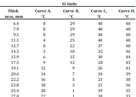
This article is based on guidelines given in EEMUA 190. Design of mounded bullet is carried out as per PD 500 as suggested in EEMUA 190 (unless specified by the customer). Other codes like ASME also can be used for design calculations. Design of shell courses for internal and external pressure at given design conditions is done as per specified design code. Selection and arrangement of stiffening ring have large impact on design thicknesses. Once bullet shell and dish end thicknesses are finalized, whole equipment is considered under following loads:

Load 1- Dead weight of the vessel (Q1)

Dead weight of the vessel is fabricated empty weight of the vessel. It is given as
Q1 (N) = Empty weight(w2) * 9.81

Load 2- Weight of liquid fill (Q2, Q2’)

Weight of liquid fill is considered for both working fluid and water. The weight of liquid is considered for 100% fill of liquid in the vessel
For operating fluid,
Q2 (N) = Density of operating fluid (kg/m3) * Liquid fill (m3) * 9.81 (m/s2)
For water,
Q2’ (N) = Density of water (kg/m3) * Liquid fill (m3) * 9.81 (m/s2)

Load 3- Internal design pressure (Q3, Q3’)

Internal design pressure is considered for both design pressure and hydro test pressure. Specified design pressure is considered along with the static head of the fluid
For design case,
Q3 (MPa) = Specified internal design pressure (MPa) + Fluid static head (MPa)
For the hydro test case,
Q3’ (MPa) = Specified hydro test pressure (MPa) + Water static head (MPa)
Where,
Static head (MPa) = Density of fluid/water (kg/m3) * 9.81(m/s2) * Fill height (m) * 10-6

Load 4- Negative internal design pressure (Q4)

Negative internal design pressure causes compressive stresses in shell plates and stiffening rings. The negative internal pressure should be taken as -0.5 bar, unless agreed otherwise specified.

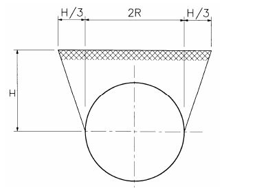
Load 5- Pressure due to the mound (Q5)

• The pressure of mound on the cylinder
The weight of the mound assumed to be resting on top of the cylinder is
Q5 (kN) = (2RH − πR2/2 + H2/3) x γs x L
Where,
γs = weight of soil per m3 (kN/m3)
H = mound depth (m)
R = shell outer radius (m)
L = Vessel T.L.- T.L. length (m)
The pressure of mound is zero at the center of the cylinder.


• Pressure by mound on domed ends
Mound exerts pressure on domed ends of the vessel. This soil pressure (ps) increases linearly with the depth.
ps (kN/m2) = C x γs x h
Where,
C = soil pressure coefficient
h = mound depth (m)
Pressure by mound on domed end is maximum at the center and minimum at the top of it.

Load 6 – Load due to the uneven support of the vessel (Q6)

Determination of uneven support, two calculations need to be made as given below using design shell thicknesses and loads Q1, Q2, and Q5.
• Using Annexure-C from EEMUA code


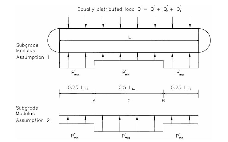
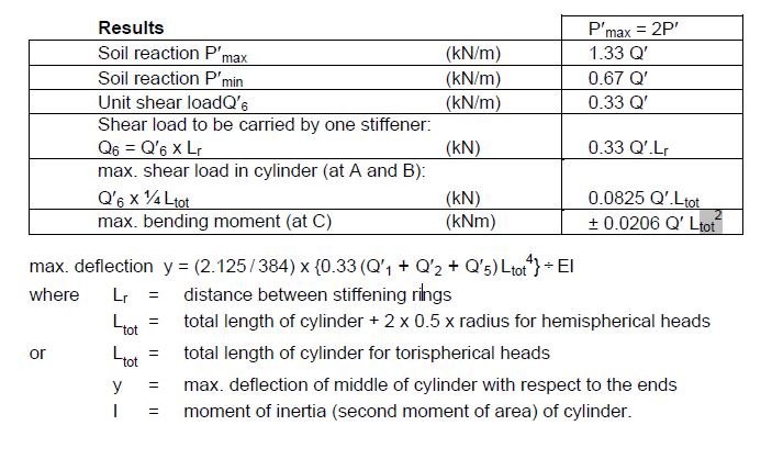
• Carry out a ‘beam on elastic foundation’ analysis, using the long-term subgrade moduli determined in the soil investigation. The calculation is usually carried out using a finite element method.
From these two calculations, governing result is to be used for the stiffener design i.e. resulting Q6.

Load 7- Load due to changes in the vessel length (Q7)

Axial loads need to be considered for the verification of longitudinal stresses. When the vessel expands or contracts due to temperature or pressure variations, the surrounding soil will exert a frictional force on the vessel. A coefficient of friction = 1 is conservative. The unit friction force Fsoil will be:
Fsoil = Q1 + Q2 + 2Q5 (kN/m)
The axial load due to friction will be maximum at mid-span of the vessel and will be equal to Fsoil X half vessel length, provided the movement of the vessel is enough to develop the full friction.
The resulting longitudinal stress due to friction will be compressive if the vessel expands, and tensile if the vessel contracts. When the vessel expands, the soil pressure on the domed ends will increase, which will result in an increased axial compressive load.

Load 8- Seismic load (Q8)

The effect of earthquakes on design loads may need to be taken into account. The effect of the horizontal acceleration should be taken into account as a horizontal lateral force. This force is equal to the percentage mentioned above of the weight (loads 1, 2 and 5). Sometimes a vertical acceleration due to the earthquake is also specified, which is taken into account by increasing the weight proportionally. The resultant of the horizontal force and the (increased) weight needs to be determined separately for loads 1, 2 and 5.

Load 9- External Pressure Caused by Explosion of Gas Clouds (Q9)

If the overpressure and the reflection coefficient are used, the pressure to be taken into account is 1.5 x 15 = 22.5 kN/m2. The load per stiffening ring is:
Q9 = (2R + ⅔ H) x L x 22.5 (kN)
Q9 may be considered as an increase in the weight of the mound and should be treated in the calculations in the same manner as Q5.

Load 10- Supporting pressure by the foundation (Q10)

The supporting load P by the sand-bed foundation to be allocated to one stiffening ring is the maximum of the two analyses: using the assumed support distribution from Appendix C and the ‘beam on elastic foundation’ approach as mentioned in Load-6
When using the assumed support distribution from Appendix C:
P = 1.33 x {Q1 + Q2 + Q5 (+ Q9, if applicable)} (kN)
When using the beam on elastic foundation approach:
P = P’ x L (kN)
where P is the maximum unit support load
It is assumed that the sand-bed will exert a radial pressure on the cylinder. The angle over which the cylinder is supported depends on the foundation, but for a properly prepared sand bed an angle of 120° is a realistic assumption.
Conservatively, it is assumed that pressures are cosine-like distributed according to:
p = p0 cos {1.5 (180° − ψ)} for 120° < ψ < 240°
The maximum pressure p0 at ψ = 180° is:
p0 = P/(1.2 x R x L) (kN/m2)


This pressure is to be added to the negative internal pressure when determining the shell plate thickness of the cylinder. During construction and initial hydro test, it may be advantageous to support the vessel on a narrower foundation, for instance, a support angle of 90° (ψ0 = 135°) or even (as a minimum) 60° (ψ0 = 150°).
For those cases the maximum pressure exerted by the foundation will be:
90° support angle: p0 = P/(0.943 x R x L) (kN/m2)
60° support angle: p0 = P/(0.65 x R x L) (kN/m2)

Bolting Torque Calculations

In order to achieve required leak-proof tightening of bolted flange joint assembly, appropriate bolt tightening method is used. Proper tightening of flange joint assembly creates compressive forces on gasket and pre-tensioning in bolts. As per bolt tightening methods or guidelines, cross tightening sequence is followed. Several cross tightening methods are available such as hand torque, slug/hand wrench, hydraulic torque, hydraulic tensioner etc.

Guidelines for bolt tightening:

As per guidelines are given in “ASME PCC-1 Guidelines for Pressure Boundary Bolted Flange Joint Assembly”, torque increments for bolt tightening are given as follows:


Target torque for bolt tightening is calculated as per ASME PCC-1, Appendix-K as follows:
Target torque, T = K*D*F
Where,
T = Target torque, N.mm (in.lb.)
K = Nut factor
D = Nominal bolt diameter, mm (in.)
F = Target bolt load, N (lb)
Example:
Let us consider 1’’ bolt of SA193 Gr. B7 is required for flange joint material with nut factor of 0.16. We will evaluate target bolt torque required for leak-proof tightening.


Bolt load calculation:
Maximum bolting torque is considered to develop 40% to 60% of bolt yield stress. Here we will consider bolt torque to produce 60% of bolt yield stress. Therefore,
Bolt load, F = A*Sy*0.60
= 0.6057*105000*0.6
= 38159.1 lb
Target torque calculations:
Target torque, T = K*D*F
= 0.16*(1/12)*38159.1
= 508.79 lb-ft.
Considering 10% bolt relaxation,
Suggested tightening torque, T = 0.9*508.79 = 457.9 lb-ft. (622.76 N-m)
Therefore, bolt tightening torque increments for considered bolts is as follows,


Impact Test Requirements as per ASME Section VIII Division 1

Carbon steel and low alloy steels show a drastic change in room temperature ductility at sub-zero temperatures. This behavior is different for different types of materials. Therefore, impact testing at such service temperatures is mandatory to ensure the strength of vessel material. ASME provides some exemption for impact testing of materials in code. Unless exempted in any of the sections mentioned, impact testing is mandatory. We will discuss some exemptions given in ASME Sec. VIII Div. 1.

ASME Sec. VIII Div.1: UG-20(f)

Impact testing is not mandatory for if they satisfy all of the following,

  • Materials are limited to P-No. 1, Gr. No. 1 or 2 and shall not exceed governing thickness 13mm for materials listed in curve A & 25mm for materials listed in curve B, C or D of Fig. UCS-66
  • The completed vessel shall be hydrostatically tested or alternatively pneumatically tested
  • Design temperature is not warmer than 345°C nor colder than -29°
  • The thermal or mechanical shock loadings are not a controlling design requirement.
  • Cyclical loading is not a controlling design requirement.


  • Fig. UCS-66 Impact test exemption curves [Ref: ASME Sec. VIII Div.1]

    ASME Sec. VIII Div.1: UCS-66(a)

    Unless exempted in UG-20(f), Fig. UCS-66 shall be used to establish impact testing exemptions for steel listed in part UCS. Impact testing is checked for the combination of minimum design metal temperature and governing thickness of the part. If the combination of MDMT and governing thickness is on or above the curve, impact testing is not required. For simplicity, the data of Fig. UCS-66 is tabulated in Table UCS-66.


    Table UCS-66: Tabular values for Fig. UCS-66
    Exemption for welded and non-welded parts are described in this section as follows:

  • The governing thickness at any welded joint exceeds 4 in. and the minimum design metal temperature is colder than 50°C, impact tested material shall be used.
  • If the governing thickness of non-welded part exceeds 6 in. and the minimum design metal temperature is cooler than 50°C, impact tested material shall be used.

  • ASME Sec. VIII Div.1: UCS-66(b)

    If coincident ratio is less than one, Fig. UCS-66.1 provides the basis to have colder MDMT that derived from UCS-66(a) without impact testing.
    Coincident ratio = tr*E / (tn-c)
    Where, tr = Design thickness
    E = Joint efficiency
    tn = Nominal thickness
    c = Corrosion allowance
    Fig. UCS-66.1 provides a reduction in MDMT without impact testing on the basis of the coincident ratio


    Fig. UCS-66.1 Reduction in MDMT without impact testing


    ASME Sec. VIII Div.1: UCS-66(c)

    No impact testing is required for the following flanges when used at minimum design metal temperature no cooler than -29°C

  • ASME B16.5 flanges of ferric steel
  • ASME B16.47 flanges of ferric steel
  • Split loose flanges of SA-216 Gr. WCB as per ASME B16.5 Class 150,300
  • Carbon and low alloy steel long weld neck flanges

  • ASME Sec. VIII Div.1: UCS-66(d))

    No impact testing is required for UCS materials 2.5mm in thickness and thinner but such exempted materials shall not be used at design metal temperatures less than -48°C.
    For vessels or components made from DN 100 or smaller tubes or pipe of P-No. 1 materials, the following exemptions from impact testing are also permitted as a function of the material specified minimum yield strength (SMYS) for metal temperatures of -105°C and warmer:


    ASME Sec. VIII Div.1: UCS-66(c)

    Unless specifically exempted in UCS-66, materials having a specified minimum yield strength greater than 450 MPa must be impact tested


    ASME Sec. VIII Div.1: UCS-68(c)

    If post weld heat treatment is performed when it is not otherwise a requirement of this division, a 17°C reduction in impact testing exemption temperature may be given to the minimum permissible temperature from Fig. UCS-66 for P. No. 1 materials.

    Post Weld Heat Treatment (PWHT) Requirement as per ASME Section VIII Division 1

    Post weld heat treatment (PWHT) is controlled process in which a material that has been welded is reheated to a temperature below its lower critical transformation temperature, and then is held at that temperature for the specified amount of time. The need of PWHT is mostly due to residual stresses and microstructural changes that occur after welding. During the welding process, a high-temperature gradient is experienced between the weld metal and parent metal. Codes like ASME specify the specific requirements for PWHT of materials. The PWHT requirements discussed in this document are in accordance with ASME Sec. VIII Div. 1.

    ASME Sec. VIII Div. 1 specifies the PWHT requirements for materials used in equipment designed as per ASME. Tables UCS-56-1 through UCS-56-11 in ASME Sec. VIII Div.1 provides heating cycle data required for PWHT of materials based on P No. and Gr. No as categorized in ASME Sec. IX. Those tables are followed by notes which provide exemptions. Table UCS-56.1 gives alternative heat treatment requirements for carbon and low alloy steels. Before applying for the detailed requirements and exemptions, satisfactory weld procedure qualifications of the procedures to be used shall be performed in accordance with all the essential variables of ASME Section IX including conditions of post weld heat treatment.

    PWHT requirements as per ASME Sec. VIII Div. 1

  • Except as otherwise specifically provided in notes of tables UCS-56-1 through UCS-56-11 or Table UCS-56.1, all welds in pressure vessels or pressure vessel parts shall be given a post weld heat treatment at a temperature not less than specified in those tables when the nominal thickness including corrosion allowance, exceeds the limits given in those Tables.
  • When the minimum design metal temperature is colder than -55°F (-48°C), and the coincident ratio defined in Figure UCS-66.1 is 0.35 or greater, post weld heat treatment is required, except that this requirement does not apply to the welded joints, in vessels or vessel parts fabricated of P-No. 1 materials that are impact tested at the MDMT
  • The exemptions provided in Tables UCS-56-1 through UCS-56-11 or Table UCS-56.1 are not permitted when post weld heat treatment is a service requirement set forth when welding ferritic materials greater than 1/8 in. (3 mm) thick with the electron beam welding process, or when welding P-No. 3, P-No. 4, P-Nos. 5A, 5B, and 5C, P-No. 10, and P-No. 15E materials of any thickness using the inertia and continuous drive friction welding processes.
  • Electroslag welds in ferritic materials over 11/2 in. (38 mm) thickness at the joint shall be given a grain refining (austenitizing) heat treatment.
  • Electrogas welds in ferritic materials with any single pass greater than 11/2 in. (38 mm) shall be given a grain refining (austenitizing) heat treatment.
  • When pressure parts of two different P-Number groups are joined by welding, the post weld heat treatment shall be of the material requiring the higher post weld temperature
  • When non-pressure parts are welded to pressure parts, the post weld heat treatment temperature of the pressure part shall control

  • Most commonly used materials for process equipment comes under P.No.-1 & Gr.No.1,2,3,4. PWHT for carbon and low alloy steels- P. No. 1 & Gr.No.1,2,3,4 are given below

    PWHT for carbon and low alloy steels- P. No. 1 & Gr.No.1,2,3,4

    Postweld heat treatment is mandatory under the following conditions

  • welded joints over 11/2 in. (38 mm) nominal thickness
  • For welded joints over 11/4 in. (32 mm) nominal thickness through 11/2 in. (38 mm) nominal thickness unless preheat is applied at a minimum temperature of 200°F (95°C) during welding. This preheat need not be applied to SA 841 Grades A and B, provided that the carbon content and carbon equivalent (CE) for the plate material, by heat analysis, do not exceed 0.14% and 0.40% respectively, where


    a. for groove welds not over 1/2 in. (13 mm) size and fillet welds with a throat not over 1/2 in. (13 mm) that attach nozzle connections that have a finished inside diameter not greater than 2 in. (50 mm), provided the connections do not form ligaments that require an increase in the shell or head thickness, and preheat to a minimum temperature of 200°F (95°C) is applied
    b. for groove welds not over 1/2 in. (13 mm) in size or fillet welds with a throat thickness of 1/2 in. (13 mm) or less that attach tubes to a tubesheet when the tube diameter does not exceed 2 in. (50 mm). A preheat of 200°F (95°C) minimum must be applied when the carbon content of the tubesheet exceeds 0.22%.
    c. for groove welds not over 1/2 in. (13 mm) in size or fillet welds with a throat thickness of 1/2 in. (13 mm) or less used for attaching non-pressure parts to pressure parts provided preheat to a minimum temperature of 200°F (95°C) is applied when the thickness of the pressure part exceeds 11/4 in. (32 mm).
    d. for studs welded to pressure parts provided preheat to a minimum temperature of 200°F (95°C) is applied when the thickness of the pressure part exceeds 11/4 in. (32 mm)
    e. for corrosion resistant weld metal overlay cladding or for welds attaching corrosion resistant applied lining (see UCL 34) provided preheat to a minimum temperature of 200°F (95°C) is maintained during application of the first layer when the thickness of the pressure part exceeds 11/4 in. (32 mm)