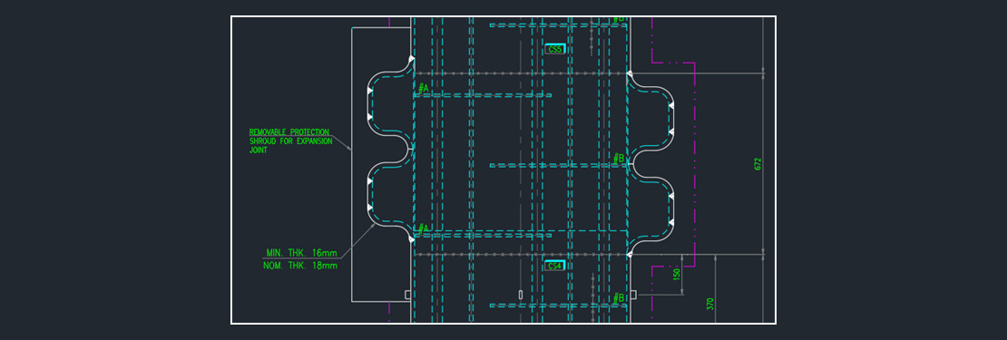
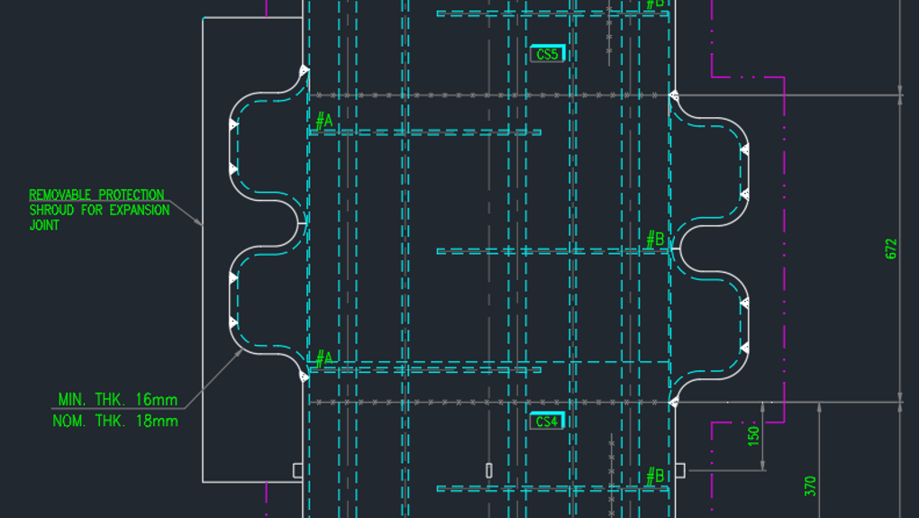
Expansion bellows are applicable to fixed tube sheet heat exchanger which help in reducing the longitudinal stresses or tube to tubesheet joint loads by allowing the axial displacement between shell and tubes. RCB-8 flexible Shell Elements (FSE) of TEMA standards deals with the calculation of spring rate and stresses induced in the FSE by using Finite Element Analysis method.
Historically for expansion bellow design, engineers used to calculate the stresses and spring rate using the plate and beam theory nut due to limitations in the plate and beam theory Finite Element Analysis method is the most widely used method for calculating the spring rate and stressed induced in the FSE.
Now let us take practical example of flexible shell element (FSE) for calculation of the spring rate –
Spring rate calculation as per TEMA RCB – 8.5 will be carried out as per following steps –
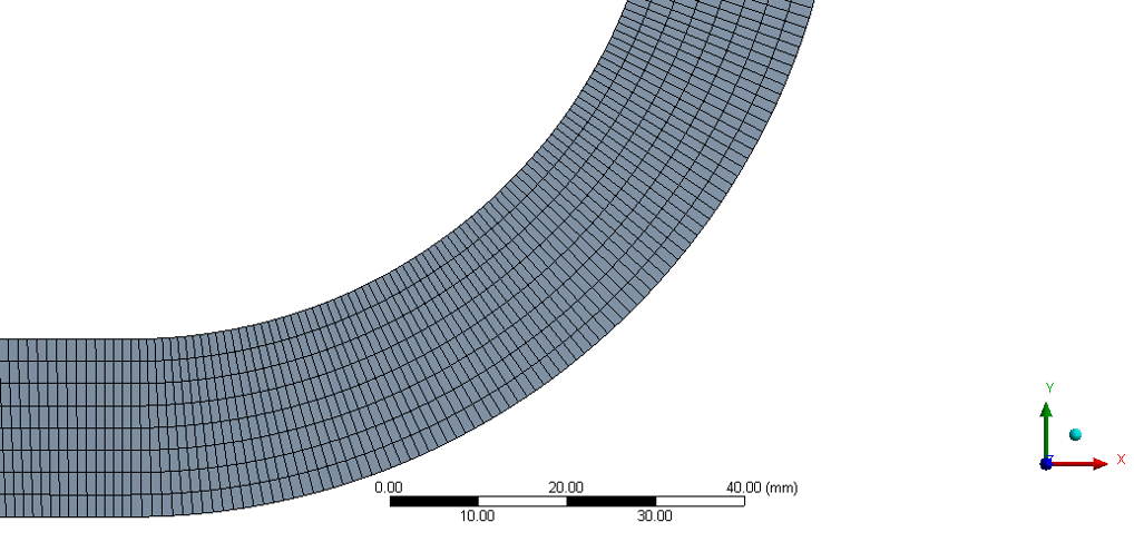
- The flexible shell element (FSE) will be modelled as per section RCB-8.2 & RCB-8.3 i.e. Axi Symmetric model will be created for Finite Element Analysis. Meshing is done in such a way that there much be at least 8 elements across the length of the flexible shell element.
- An axial load Faxial as described in RCB-8.42 shall be applied at the smaller end of end FSE.
Faxial will be calculated as per (p/4) x G2 x 100 lbf/in2. We need to model dummy flange at the smaller end by considering the shell up to the minimum length of 2.5SQRT(RT) of the FSE to reduce the stress concentration factor in the stresses induced.
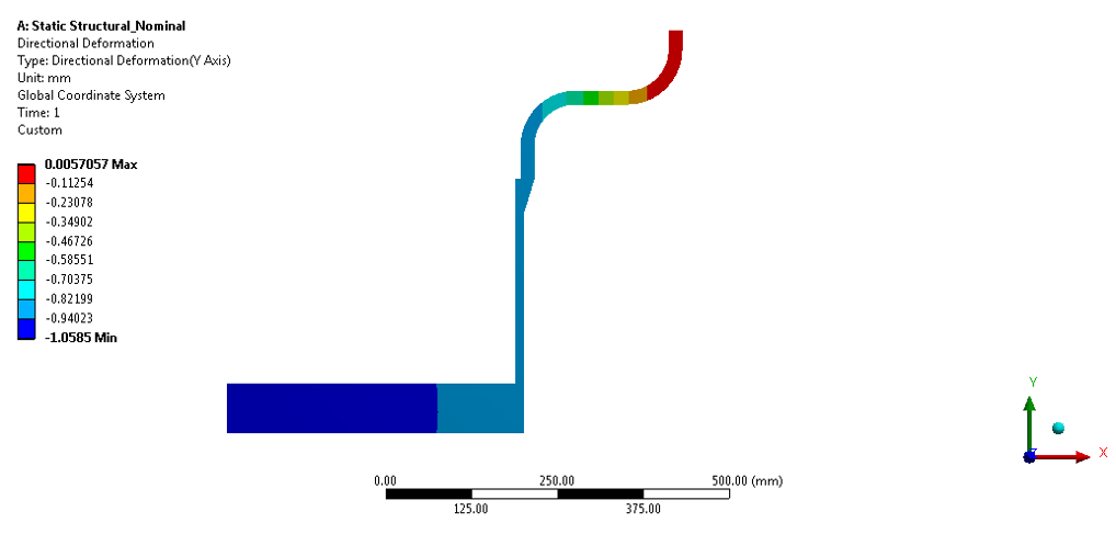
- Finite Element Analysis will be performed and displacement in the axial direction (d) shall be noted for the applied force (Faxial).
- The spring rate of the axi symmetric FSE, KAS will be computed as force applied (Faxial) / displacement induced (d).
- The Spring rate of the entire FSE is KFSE = KAS/2
- When only one FSE is present then the spring rate is given by K FSE above. When multiple FSE’s are present, the spring rate is given by
KE = 1/ ((1/KFSE1) + (1/KFSE2) + …. (1/KFSEn))
Where KE is the equivalent spring rate of the entire system.
Most important – Spring calculation to be done for nominal and minimum condition of thickness for corroded and un-corroded condition.
EXPANSION BELLOW SPRING STIFFNESS CALCIULATION (NOMINAL-UNCORRODED)
Preliminary analyses based on the application of a unit axial load as per above steps is carried out to evaluate spring rate of the bellow.
Un-corroded condition at design temperature
SHELL ID 840 mm
F axial 382091.5365 N
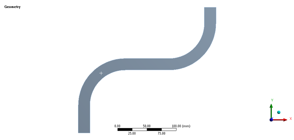
Axisymmetric Geometry of Bellow (Un-Corroded) as TEMA RCB 8
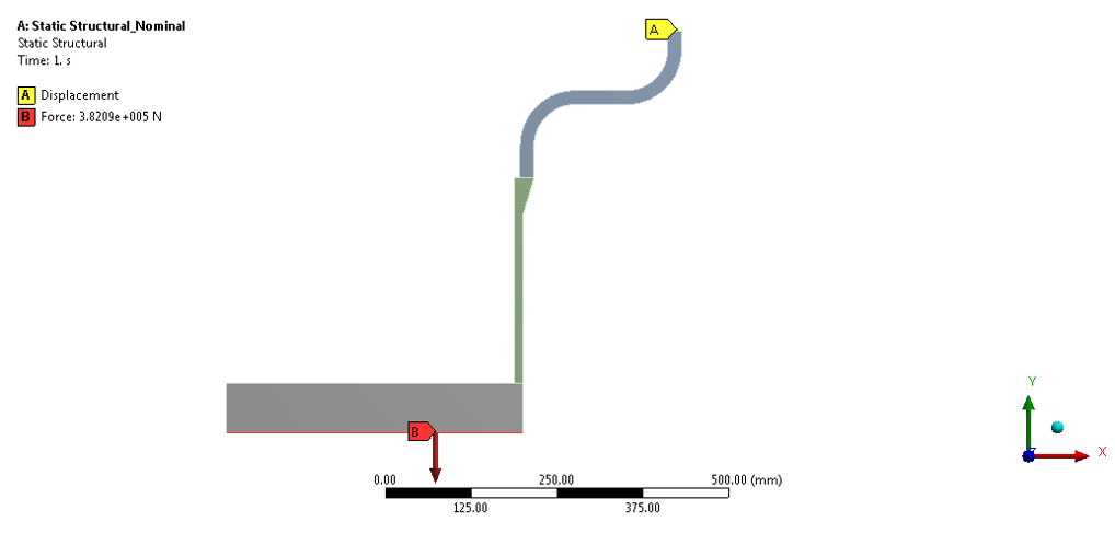
SHELL ID 840 mm
F axial 382091.5365 N
Deflection 1.0585 mm (refer above figure)
KFEA = 360974.5266 N/mm
KFSE = ¼ * KFEA = 90243.63166/mm ( for Nominal Un-Corroded )
Similarly, Calculate spring rate for all remaining cases i.e. nominal corroded case, minimum un-corroded and minimum corroded case.
| Nominal Un-corroded | Nominal Corroded | Minimum Un-corroded | Minimum Corroded | |
| Stiffness (N/mm) | 90243.63166 | 66455.6724 | 67929.79954 | 44986.70738 |