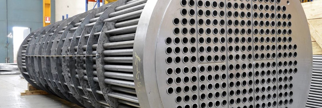
Tube sheets are used as supporting element and isolating tubes from each other in heat exchangers and boilers. Tube sheets are made from the round flat piece of plate (sheet) with holes drilled. The tube sheet should be customized designed by the engineer especially for each process equipment depending on the type of application and its design data. The tube hole pattern or pitch on tube sheet is always varied as per requirement of the design.
Tubes are attached with the tubesheet with the help of hydraulic expansion between tube sheet holes and weld at the corner face of the tube sheet along channel side of the heat exchanger. Tubesheets are the most supporting part of the tubes which avoid intermixing of the shell side and channel side fluids by providing compartments and helps in reducing vibration of the heat exchanger by allowing proper flow through tubes. Tube patterns on the tubesheet help in heat transfer process by allowing the fluid pass through each tube as per the patterns drilled on the tube sheet. Tube patterns and pitch is the most important and complex part of the tubesheet design which decides the heat transfer in the heat exchanger.
Nowadays the design is mostly automated with help of Design software i.e. PV Elite for Vessel design as per ASME Section VIII Div 1 & 2 (UHX for tubesheet design), Tubular Exchanger Manufacturing Association (TEMA) and 3D modeling using CAD software. CAD software allows the engineer to find more accurate and precise hole pattern or pitch of the tubes. In 3D CAD software the command “fill pattern” helps the designer to achieve the accurate pattern in most optimum way and time.
Generally, there are 4 Nos. of tube patterns as per TEMA Standards i.e.
Below image shows tube patterns as per TEMA standard –
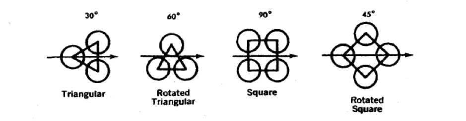
Figure A – Tube Pattern as per TEMA Standard
How to Create Fill Pattern in Solidworks Software
Now we will see the steps to create fill patterns in Solidworks software.
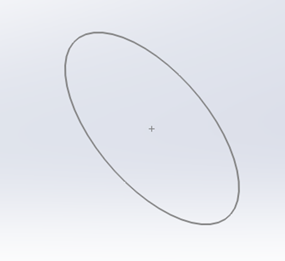
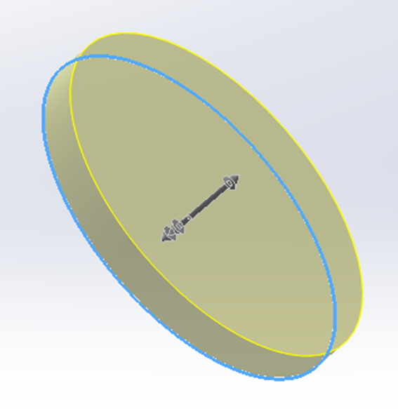
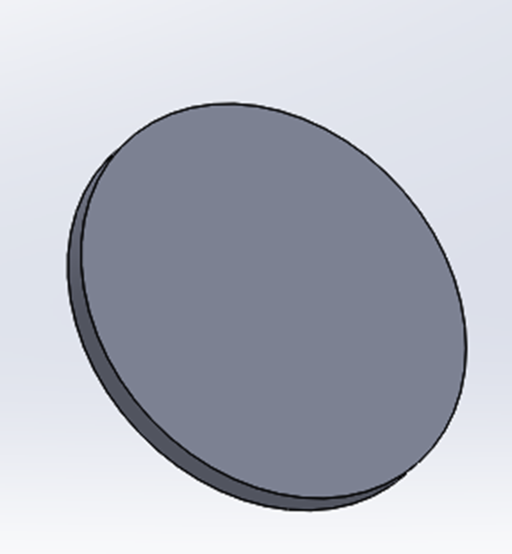
Step 1 – Create a tubesheet circle of diameter “D” and tubesheet thickness “t”
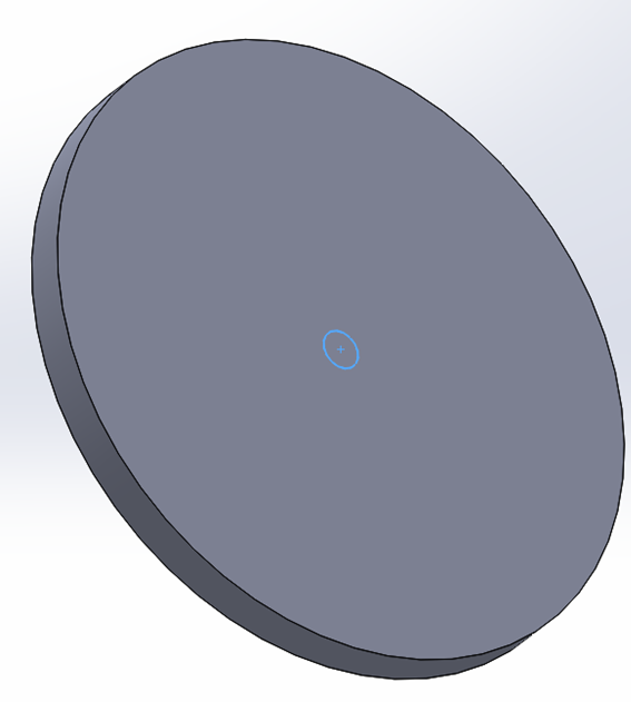
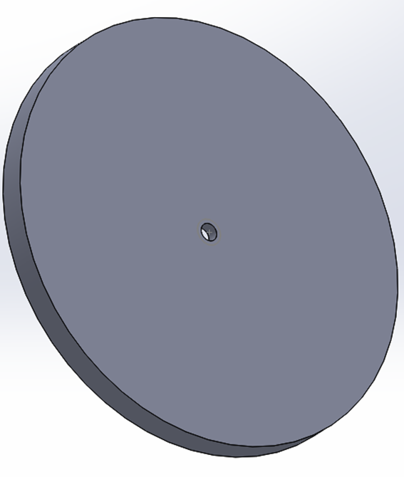
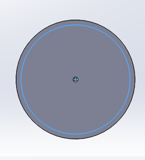
Step 2 – Create a hole on the tubesheet of tube diameter “d” and create cut through tubesheet
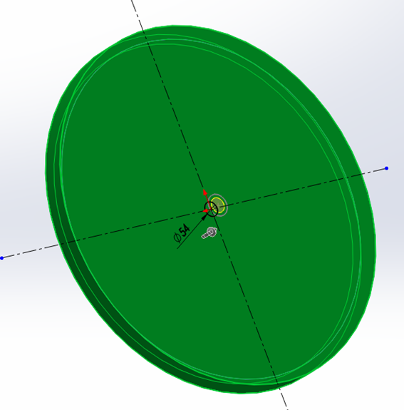
Step 3 – Draw the Outer Tube Limit (OTL) Circle on the tubesheet face as below
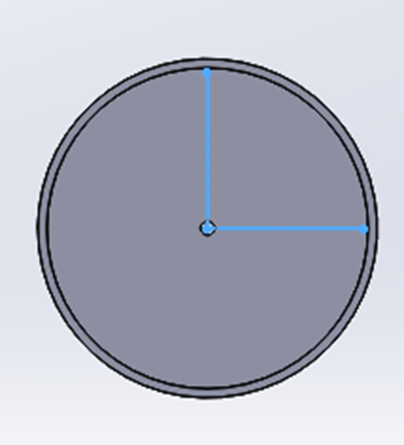
Step 4 – Draw the line on the tubesheet face for tube fill pattern
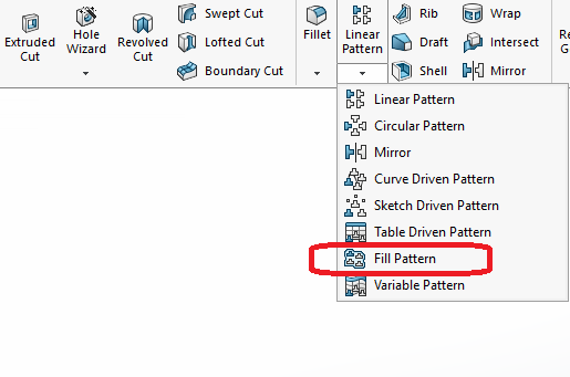
Step 5 – Create fill pattern from Solidworks Feature List
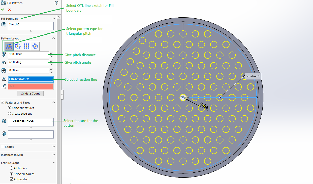
Step 6 – Enter require input for fill pattern as per the below
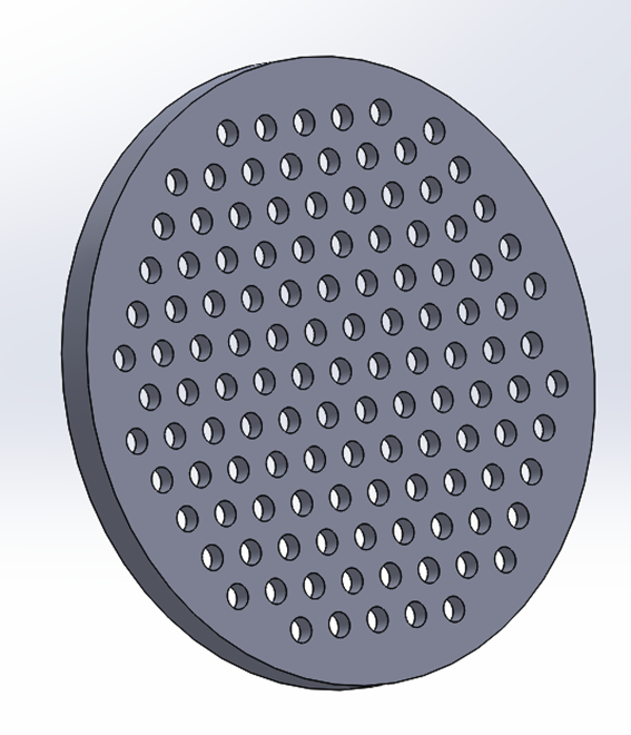
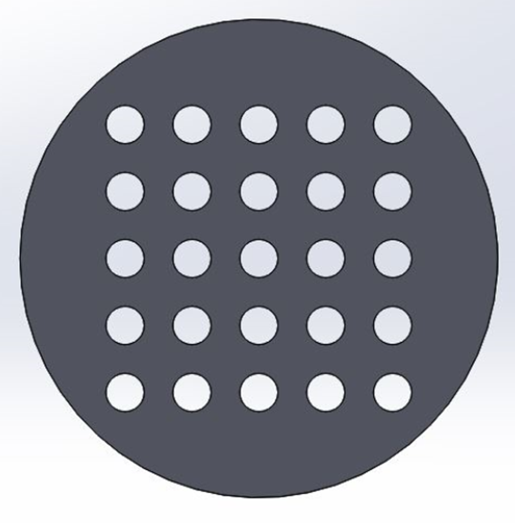
Fill Pattern Results –
• Triangular Pattern
• Rotated Triangular Pattern

• Square Pattern
• Rotated Square Pattern