Theoretical Background:
Mixing is one of the common unit operations in chemical industries. The essential task of mixing equipment is to bring together two or more fluids/solids which are initially separated. McCabe rightly quoted “Many processing operations depend for their success on the effective agitation & mixing of fluids”. Desired mixing process could be Multiphase or Single phase, reacting or non-reacting, laminar or turbulent, isothermal or non-isothermal depending upon materials. Mixing could be accomplished either by rotating impellers or by liquid Jet. Mixing by Impellers explained here. The purpose of this blog is to give an overview on topic “Theoretical & Computational Fluid Mixing using Jet”.
In jet mixing, part of the liquid from the tank circulated into the tank at high velocities with the help of pumps through nozzles. Due to the nozzle, surrounding fluid entrains and creates a circulatory pattern, which leads to mixing in the tank as shown in Figure. 1.
Figure 1. Working of an Eductor
Comparing to conventional impellers, jet mixers have several advantages such as no moving parts as in conventional agitators, reducing maintenance costs, and it is easy to install when compared with impellers. Eductor consist of a nozzle followed by diffuser, as shown in Figure. 2. The fluid passing which pass through the nozzle section is called as motive fluid and fluid which is being entrained due to high motive velocity is called as entrain fluid. Here the ratio of motive to entrain fluid is 1:4.
Figure 2. Eductor consisting two sections Nozzle followed by Diffuser
Problem Definition:
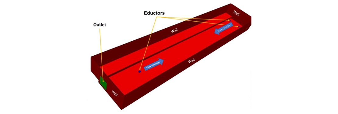
The selected problem consists of a large rectangular waste water tank with three eductors submerged in the wastewater as shown in Figure. 3 below. The tank is 15-meter-long and 2.8-meter height. The mixing characteristics in the tank is strongly coupled with the kinetic energy transformation by eductors. Therefore, it is desirable to know the accurate flow rate from eductor. The total flowrate from the diffuser section of eductor is calculated from energy balance.
Figure 3. Geometry of Large Rectangular Tank with Three Eductors
Numerical Model, Meshing and Initial & Boundary Conditions:
Computational Fluid Dynamics is very useful to assist in the design, optimization and scale-up of mixing tanks. Still, there are some difficulties which have been countered by some approximation of the physical phenomena, such as turbulence model, rheological models, ideal boundary conditions etc. The generalize equations solved in a mixing calculation i.e. conservation of mass, momentum and energy can be found in a standard chemical engineering books. Fundamental CFD approach can be found in fundamental CFD books.
Figure. 4 depicts the generated mesh for the numerical analysis. Mesh is finer near eductors outlet due to large gradients and coarser in elsewhere. Most of industrial mixing tank problems involves turbulent flow, vortices and circulation therefore, resolving of such flow phenomena should be utmost priority while model selection. The standard k-epsilon & k-omega model has been criticized for poor performance with swirling or recirculating flow occurs in mixing tank. The Curvature Correction (CC) modification to k-omega model accounts re-circulation and vortices and hence same has been utilized in this study. Multiphase model selected for the analysis with two fluids having same properties; one fluid is already inside the tank and other is pumped using eductor. Interaction of two fluids provides mixing characteristics. The boundary conditions selected are shown in Table. 1.
Figure. 4 Generated Mesh for Rectangular Tank with Three Eductors
Table 1. Initial & Boundary Conditions
Results & Discussion:
The study has been carried out to find mixing characteristics using eductor pump in large rectangular tank. The analysis has been carried out to optimize the mixing in the tank with respect to number of eductors, position and angle of eductors. Here, the eductors positioned at a position from the bottom of the tank has been discussed only.
Volume fraction of fluid from the eductors noted at different locations in the tank provides the mixing characteristics and interaction two fluids very well. Figure 5 provides wastewater volume fraction (from eductor) over the line passing from the center of one of the eductor respectively at time 1200 secs. From Figure 5. it can be concluded that the three eductors have provided the enough kinetic energy for mixing in a given time of 1200 secs. Each eductor has shown the capacity to drive the fluid for 10 to 11 meter in the compartment. The pumped fluid fraction in middle of the tank is found to be in the range of 0.45 to 0.5, which conforms the strong momentum force acting in this section. With current eductor position it can be concluded that the linear momentum energy transfer is dominant and therefore strong linear mixing has occurred only in the tank. At corners and at the back of all three eductors, negligible momentum transfer has been observed (i.e. zero fraction). Figure. 6. depicts the wastewater fraction over the horizontal section at the definite height interval from bottom to top. Figure 6. also, supports the statements concluded from Figure. 5 in border way.
Figure. 5 Volume fraction over the length of the tank length
Also, check the video below for more information about jet fluid interaction in the tank.